Motion Tracking Turret
Design Status - In progress
The Motion Tracking Turret consists of a microcontroller, three ultrasonic range-finders, a motor, a mount, and a couple other small circuit components. The turret will follow any motion in the environment and shoot at it.
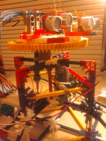
A prototype, shown at the left, has already been constructed and tested using the C8051 microprocessor. The prototype did not have an infrared emitter, but the motion tracking algorithm worked sufficiently well. A document detailing the construction and functionality of the prototype is available below under motion_tracking_turret.doc.
The Motion Tracker works by keeping track of its position with and comparing stored environment data to current environment data. A potentiometer is connected to the tracker mount such that it rotates as the mount rotates, so the voltage from the potentiometer varies as the mount moves. This allows the voltage from the potentiometer to be used as positioning data. The environment data is provided by three ultrasonic range finders. Having three ultrasonic range finders allows an object to be tracked and centered on.
For the game, two motion trackers will be created, a Smart Tracker and a Simple Tracker. The Simple Tracker will scan the area until the rangers stop pinging out (until something moves in front of them). The Simple Tracker will shoot at and track the movement until it is out of range. The Simple Tracker can be easily stopped by placing an object anywhere within its range. The Simple Tracker will permanently lock on and shoot at the object placed in front of it. The Smart Tracker has an EMI (External Memory Interface) to save data about the environment. The Smart Tracker begins by initializing the environment; the tracker sweeps across the space in front of it, saving the distance data from the rangers at each position. The tracker then scans the environment, checking for differences between the saved environment data and the new data from the environment. If an anomaly is detected, the tracker will follow and shoot at the moving target. If an object is placed in front of the turret for over a set amount of time, the tracker will add the object to its environment and begin scanning again.
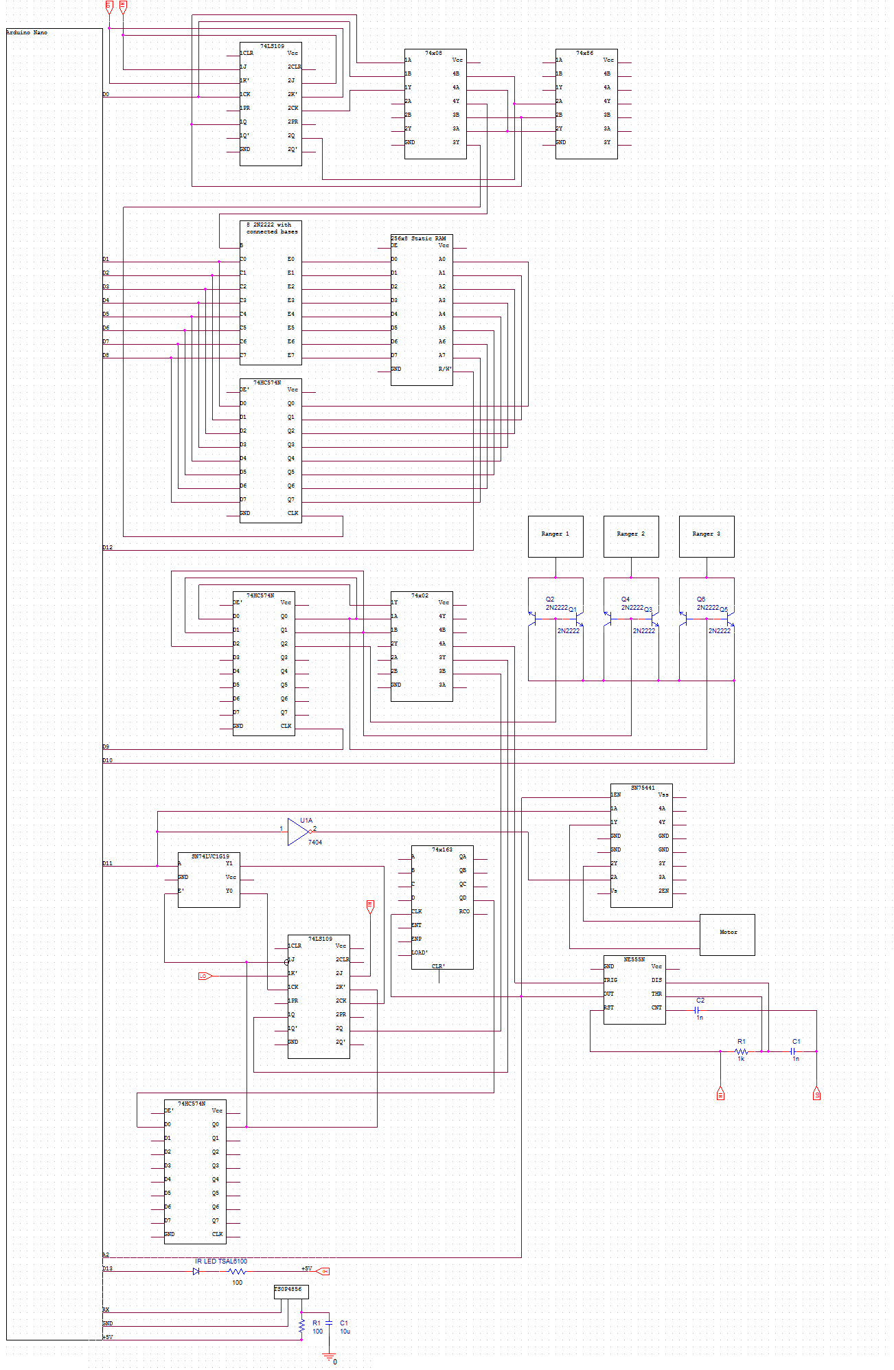
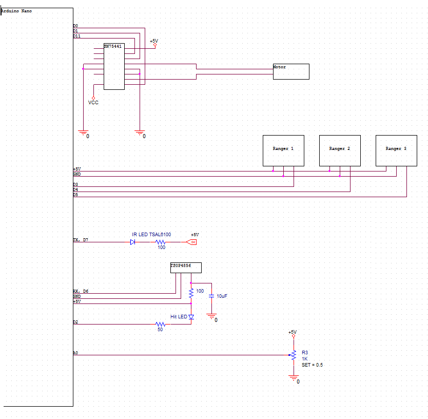
A partial circuit schematic for the the Smart Turret implemented on an Arduino Nano is provided in the document SmTracker_Schematic.png below. Complete schematic and code for the Simple Tracker is provided in STracker_Schematic.png, and STracker_Code.ino.
The Motion Tracking Turret consists of a microcontroller, three ultrasonic range-finders, a motor, a mount, and a couple other small circuit components. The turret will follow any motion in the environment and shoot at it.
A prototype, shown at the left, has already been constructed and tested using the C8051 microprocessor. The prototype did not have an infrared emitter, but the motion tracking algorithm worked sufficiently well. A document detailing the construction and functionality of the prototype is available below under motion_tracking_turret.doc.
The Motion Tracker works by keeping track of its position with and comparing stored environment data to current environment data. A potentiometer is connected to the tracker mount such that it rotates as the mount rotates, so the voltage from the potentiometer varies as the mount moves. This allows the voltage from the potentiometer to be used as positioning data. The environment data is provided by three ultrasonic range finders. Having three ultrasonic range finders allows an object to be tracked and centered on.
For the game, two motion trackers will be created, a Smart Tracker and a Simple Tracker. The Simple Tracker will scan the area until the rangers stop pinging out (until something moves in front of them). The Simple Tracker will shoot at and track the movement until it is out of range. The Simple Tracker can be easily stopped by placing an object anywhere within its range. The Simple Tracker will permanently lock on and shoot at the object placed in front of it. The Smart Tracker has an EMI (External Memory Interface) to save data about the environment. The Smart Tracker begins by initializing the environment; the tracker sweeps across the space in front of it, saving the distance data from the rangers at each position. The tracker then scans the environment, checking for differences between the saved environment data and the new data from the environment. If an anomaly is detected, the tracker will follow and shoot at the moving target. If an object is placed in front of the turret for over a set amount of time, the tracker will add the object to its environment and begin scanning again.
A partial circuit schematic for the the Smart Turret implemented on an Arduino Nano is provided in the document SmTracker_Schematic.png below. Complete schematic and code for the Simple Tracker is provided in STracker_Schematic.png, and STracker_Code.ino.
Prototype
|
Smart Tracker
|
Simple Tracker
| ||||||||
Player Control Generic (Sensor Pack and Shooter)
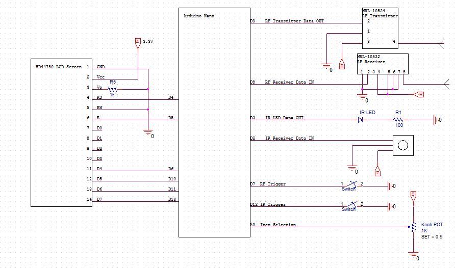
The player control manages the damage to and from the player. It keeps track of the player's items, stats, and status conditions. Right now, the player control device consists of a microcontroller, IR input and output devices, RF input and output device, and some buttons and lights. Below are the schematic (playercontrol.png) with the Arduino Uno microcontroller and the code for the device (playercontrol.ino).
|
| ||||
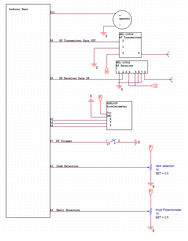
Player Control Caster (RF Transmitter and Hand positioning sensor)
The caster player control only has an RF transmitter (no IR transmitter). The output signals of the RF transmitter is controlled by a potentiometer and an accelerometer attached to one hand of the player. The potentiometer is connected such that it's rotation is controlled by the wrist's rotation. The strength of the spell while casting is proportional to the acceleration of the hand, and the position of the potentiometer determines which spell is cast.
|
| ||||
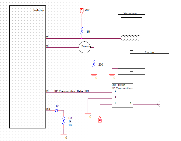
Traps
A trap is any environmental (non-player) hazard. The trap we have shown below is a tension trap; it is mouse trap with a string attached that when set off deals damage through an rf transmitter to players. The schematic is on the left, and the code to be uploaded to the arduino is on the right.
|
| ||
